AFR 245cc SBC photos and molds
Moderator: Team

Re: AFR 245cc SBC photos and molds
This separation without a flow loss is throwing me for a loop. I have had ports separate, lose flow, and then open the valve more and then the flows more. I would expect to see a bump or dip in the flow curve would I not?
Theoretical open question: Would it be possible for the port with the red flow line below to be separating even though the curve goes up smoothly?
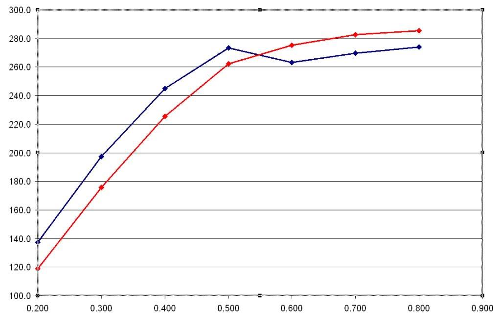
Theoretical open question: Would it be possible for the port with the red flow line below to be separating even though the curve goes up smoothly?
Last edited by MrBo on Fri Jul 27, 2012 3:18 pm, edited 1 time in total.
"I promise you Sheriff, I won't throw one more rock... Didn't say nothin' 'bout no brick!" --Ernest T Bass
Re: AFR 245cc SBC photos and molds
Chad, I understand the pitot mode and calibration. The second last bench I built was a pitot bench. I used the FP1 in pitot mode with calibrations for the flow and areas inside the pipe. I still have that pipe with the pitot in and the calibrations for pitot mode in the software.cspeier wrote: I understand, but you can still hook the pitot up and use PS1 and PS2, even without the manometer mode to do your probing. Then you can use "v" to calibrate it in.
I have no idea why you would need to use calibrations when using a pitot to probe for local velocities.??
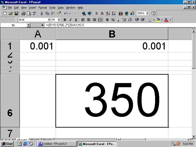
The method I used for fps numbers was as simple. I typed one formula into one cell; B6 in the pic below.
It was simple to do.
I know exactly was it being calculated and how.
Cell A1 (plenum pressure) and cell B1 (differential) were already there when I opened the spreadsheet, and being fed live data.
This way (manometer mode), I can also see when I am about to peg the differential transducer. The standard unit is only rated to go up to about 38”or 40”.
28” of plenum pressure and 419 fps impact pressure is 40” on the differential transducer.
I pitot tested at about 20” and it self corrects to 28”.
Take a look at the screen grab below. No second guessing, it is almost like looking at water manometers on the wall with the fps right below.
"I promise you Sheriff, I won't throw one more rock... Didn't say nothin' 'bout no brick!" --Ernest T Bass
-
SchmidtMotorWorks
- Vendor
- Posts: 11003
- Joined: Mon Apr 11, 2005 2:30 am
- Location: CA
Re: AFR 245cc SBC photos and molds
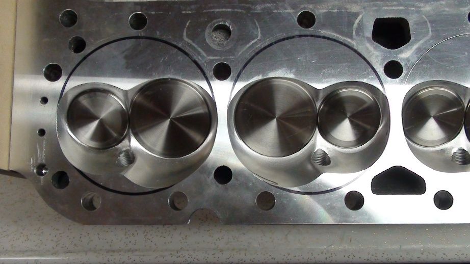
Just for curiosity, here is what a raised port looks like with the same dimensions.
You do not have the required permissions to view the files attached to this post.
Helping to Deliver the Promise of Flying Cars
-
SchmidtMotorWorks
- Vendor
- Posts: 11003
- Joined: Mon Apr 11, 2005 2:30 am
- Location: CA
Re: AFR 245cc SBC photos and molds
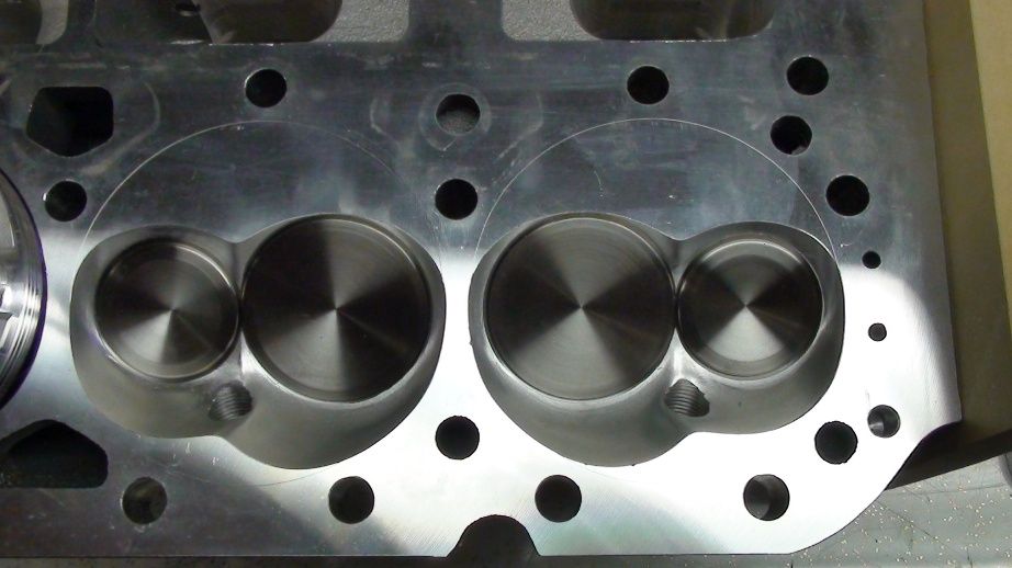
Std port
You do not have the required permissions to view the files attached to this post.
Helping to Deliver the Promise of Flying Cars
-
USMC_Spike
- Pro

- Posts: 264
- Joined: Tue Mar 06, 2012 12:53 pm
- Location: MotorKraft Mit Uns - East of the Pecos, Tejas
Re: AFR 245cc SBC photos and molds
Ok, that is why in the port valve pocket they have the shear dams...to shear the fuel back into the airstream!KnightEngines wrote:...where you have areas of lower activity you can form fuel droplets - particularly at lower rpm (where velocity is lower to start with), surface finish & the angles of the valve job can be used to shear that fuel back into the airstream.
So this is why all the emphisis on having a good short side turn. What is the "correct" shape? It seems from what I've readKnightEngines wrote: The most common spot for turbulence/seperation is over the short turn where the air turns down into the cylinder, the shape of the turn can be critical in keeping the flow attatched to the surface & following the shape of the turn - when the air gets too fast or the shape is wrong it'll stop following the shape of the turn, jump off & start interfering with flow.
we want a constant radius on it? Ideal?
What is the difference with the following:
.....Constant radius on the short side turn?
.....Increasing radius on the short side turn? (Where the turn gets less as you move from the port towards the valve)
.....Decreasing radius on the short side turn? (Where the turn gets greater as you move from the port towars the valve)
By pushing the air toward the roof, we hope to accomplish flow over the radius that doesn't get "turbulent" (theKnightEngines wrote: The intake manifold can play a big part in it as well, it can be used to set up the flow into the port in such a way as to push air into the areas that are less active on a bare head with a radius entry. Push the air towards the roof of a port that is too fast over the turn & you can unload the turn a bit & hold of turbulence to higher lift/flow.
unwanted interference type) until a higher RPM that we don't intend to use. So if we want to use the power curve up to 7000 RPM, add 500 RPM for the
shift point 7500 RPM, We'd probably want to have the onset of separation at say 8000 or 8500 RPM or more? If I understand you?

FOUND: new improved smaller non-ricer pic
-
SchmidtMotorWorks
- Vendor
- Posts: 11003
- Joined: Mon Apr 11, 2005 2:30 am
- Location: CA
Re: AFR 245cc SBC photos and molds
What does "pushing the air toward the roof" mean?By pushing the air toward the roof,
Does it mean increasing velocity near the roof?
If so, how would you accomplish that?
Helping to Deliver the Promise of Flying Cars
Re: AFR 245cc SBC photos and molds
Little update:
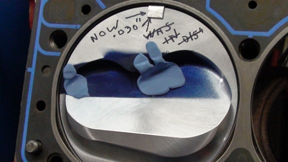
I bought some new JE pistons with bigger domes (10.8cc) and .043" rings for a 4.125” bore. (Old dome on the 400 ci was 3cc with a 60cc chamber). They didn't quite fit the valve locations though.
I since learned there were other pistons that may have fit, but they had 1/16” rings.
I probably should have bought custom pistons for these heads.( I wanted to use .043" rings and a vacuum pump)
I take more pics now and less notes.
.
.
A little grinding.
.
More pistons
.
.
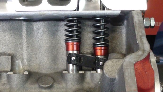
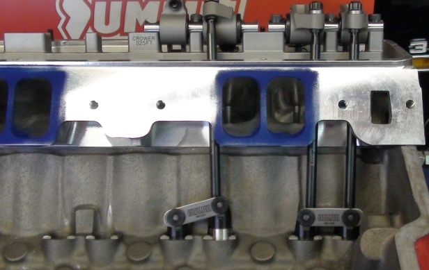
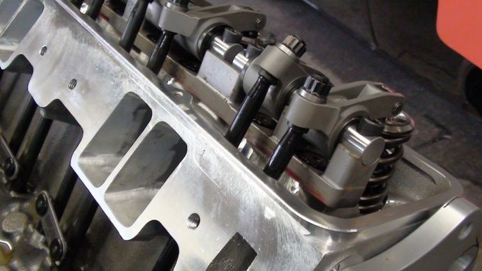
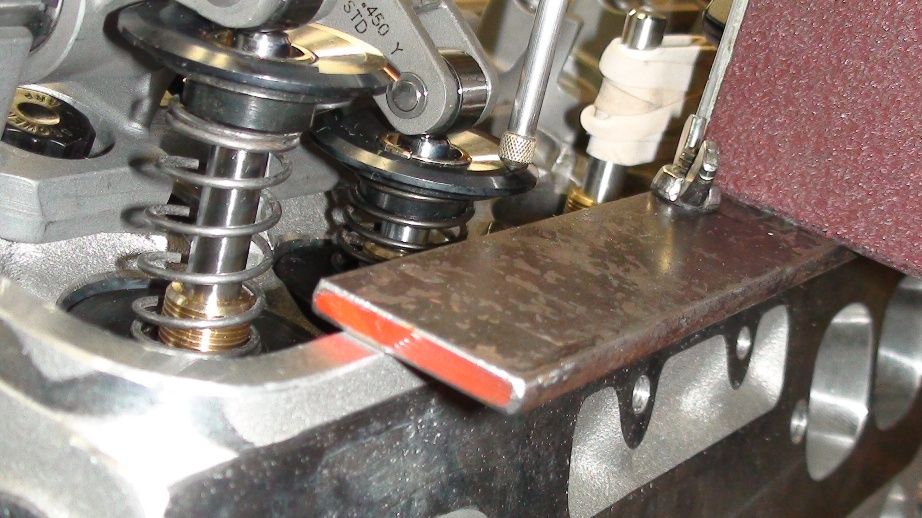
I thought I might try to use my rev kit since since I bought rockers with a .550" offset. You can use non offset lifters with a .550" intake offset. I ended up using bigger pushrods & offset lifters & no rev kit.
.
.
.
.
.
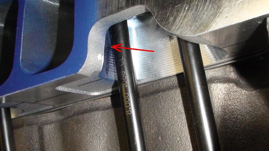
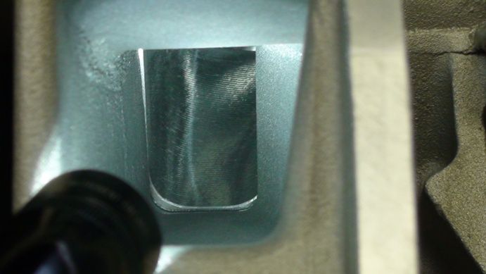
The red arrow above is the area that would need a bit of grinding if you tried to use a standard lifter, with a 3/8” pushrod, .550” offset rocker & a rev kit.
A 5/16” pushrod would fit.
Grinding for the 3/8” pushrod would have left the port wall very thin there, and I was concerned about the pushrod rubbing through while running & the port sucking in oil.
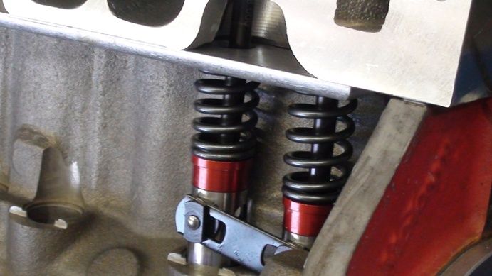
So I went with the offset lifters below, and ended up with a boat load of clearance.
.
.
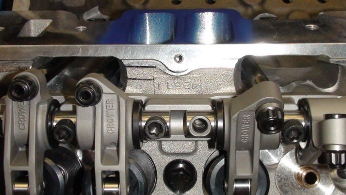
Rocker offset
.
I bought some new JE pistons with bigger domes (10.8cc) and .043" rings for a 4.125” bore. (Old dome on the 400 ci was 3cc with a 60cc chamber). They didn't quite fit the valve locations though.
I since learned there were other pistons that may have fit, but they had 1/16” rings.
I probably should have bought custom pistons for these heads.( I wanted to use .043" rings and a vacuum pump)
I take more pics now and less notes.

.

.
A little grinding.

.
More pistons
.

.
I thought I might try to use my rev kit since since I bought rockers with a .550" offset. You can use non offset lifters with a .550" intake offset. I ended up using bigger pushrods & offset lifters & no rev kit.
.

.

.

.
.
The red arrow above is the area that would need a bit of grinding if you tried to use a standard lifter, with a 3/8” pushrod, .550” offset rocker & a rev kit.
A 5/16” pushrod would fit.
Grinding for the 3/8” pushrod would have left the port wall very thin there, and I was concerned about the pushrod rubbing through while running & the port sucking in oil.
So I went with the offset lifters below, and ended up with a boat load of clearance.
.

.
Rocker offset
.

"I promise you Sheriff, I won't throw one more rock... Didn't say nothin' 'bout no brick!" --Ernest T Bass
Re: AFR 245cc SBC photos and molds
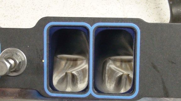
The T Ram intake didn’t quite line up with the ports.
.
1270 Felpro Gasket
.
.
Ground the port entrances so they would fit several different intakes I have. Changed to titanium retainers as well.
Put a 2970 intake on. Engine is in my brothers drag car. Maybe go to track soon….
.

.
1270 Felpro Gasket

.
.
Ground the port entrances so they would fit several different intakes I have. Changed to titanium retainers as well.

Put a 2970 intake on. Engine is in my brothers drag car. Maybe go to track soon….

.
"I promise you Sheriff, I won't throw one more rock... Didn't say nothin' 'bout no brick!" --Ernest T Bass
-
swatson454
- Guru

- Posts: 1500
- Joined: Thu Sep 03, 2009 6:06 pm
- Location: Dripping Springs, Texas
Re: AFR 245cc SBC photos and molds
Me like pictures. Pictures good. 
It looks really good, man!
Shawn
It looks really good, man!
Shawn
Live in such a way that those who know you but don't know God will come to know God because they know you.
-
JoePorting
- Guru
- Posts: 2997
- Joined: Mon Jun 14, 2010 3:16 pm
- Location: Lake Elizabeth, CA
Re: AFR 245cc SBC photos and molds
If you raise the floor, you push the air toward the roof of the port. The objective there is to increase the radius of the short turn radius so as to increase the amount of air using the short turn side of the valve. As your CFD model shows in blue, that part of the valve is not being used in the low port version. But it's a bit of a zero sum game because the more you increase the floor, the more the air has to turn. This is where this part of the floor because very touchy.SchmidtMotorWorks wrote:What does "pushing the air toward the roof" mean?By pushing the air toward the roof,
Does it mean increasing velocity near the roof?
If so, how would you accomplish that?
Joe Facciano
Re: AFR 245cc SBC photos and molds
Good, glad to here that. I will post some more laterswatson454 wrote:Me like pictures. Pictures good.
It looks really good, man!
Shawn
I wasn’t sure about posting too many at once, or too high of resolutions, as I thought the pages might load slowly on some internet systems.
"I promise you Sheriff, I won't throw one more rock... Didn't say nothin' 'bout no brick!" --Ernest T Bass
Re: AFR 245cc SBC photos and molds
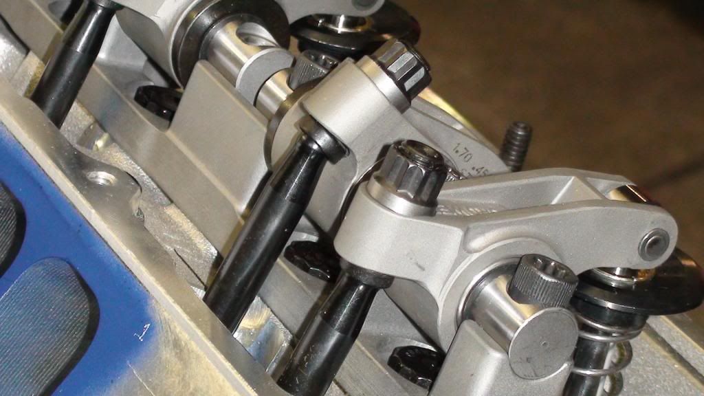
Here’s a higher resolution pic of an intake rocker and the 210 degree ball end on the pushrods I used.
.
http://i956.photobucket.com/albums/ae45 ... 34d56e.jpg
.
It also occurred to me that my rockers say .450” offset on the side of them, not .550” like it says on my bill.
I haven’t quite figured that out yet. I will measure them next time the rocker covers are off.
.
.
.
http://i956.photobucket.com/albums/ae45 ... 34d56e.jpg
.
It also occurred to me that my rockers say .450” offset on the side of them, not .550” like it says on my bill.
I haven’t quite figured that out yet. I will measure them next time the rocker covers are off.
.
.
"I promise you Sheriff, I won't throw one more rock... Didn't say nothin' 'bout no brick!" --Ernest T Bass
Re: AFR 245cc SBC photos and molds
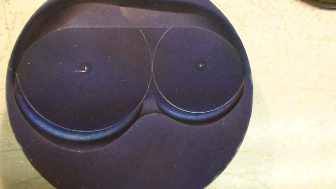
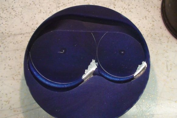
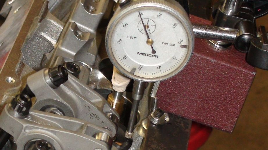
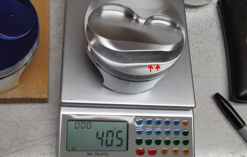
I seen this trick for checking piston domes in the Reher-Morrison engine book.
.
.
.
I used a longer pin than came with the pistons for checking the fit.
.
.
.
I used a longer pin than came with the pistons for checking the fit.
"I promise you Sheriff, I won't throw one more rock... Didn't say nothin' 'bout no brick!" --Ernest T Bass
Re: AFR 245cc SBC photos and molds
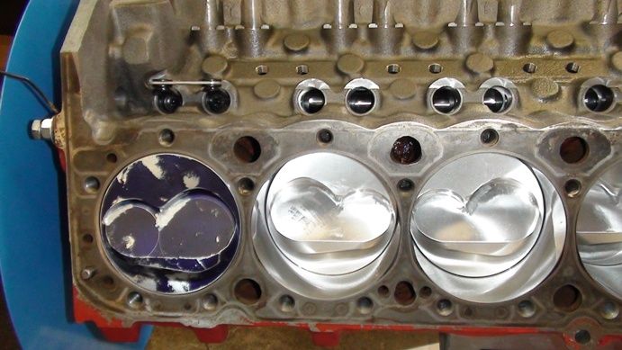
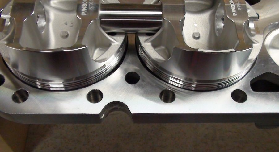
Pistons hit the chambers a wee bit around the radius at red arrows.
.
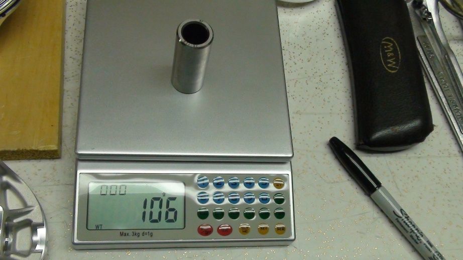
Light 2.25” long pins too.
.
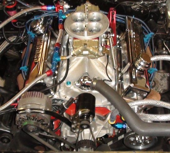
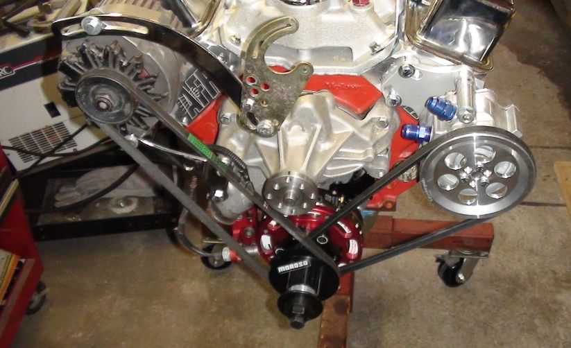
Another engine photo. Note the high teck "state of the art", Canadian Tire furnace fan belts.
.
Light 2.25” long pins too.
.
Another engine photo. Note the high teck "state of the art", Canadian Tire furnace fan belts.
"I promise you Sheriff, I won't throw one more rock... Didn't say nothin' 'bout no brick!" --Ernest T Bass