Chamber shaping-How good/bad can this be made to work?

General engine tech -- Drag Racing to Circle Track

Moderator: Team

Post Reply
Xnke
Pro
Pro
Posts: 343
Joined: Mon Aug 20, 2012 7:39 pm
Location:

Chamber shaping-How good/bad can this be made to work?

Post by Xnke »

Another thread here brought up a question that I have been meaning to ask, and after cluttering that thread it was recommended I start a new one.

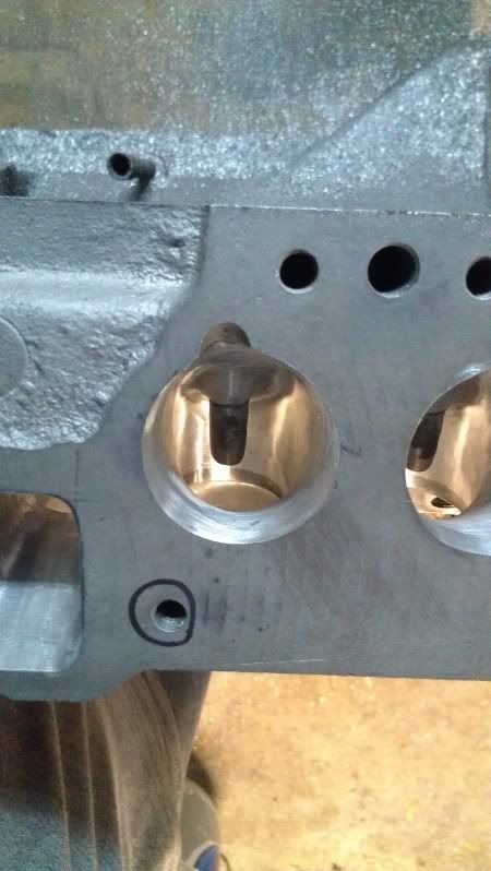
So, this is the combustion chamber of my current cylinder head, and I am thinking that it can be better. it's 55cc volume, bores are 88mm and the piston is dished with a quench band around the outer 4mm of the piston, over the ring pack.

Image

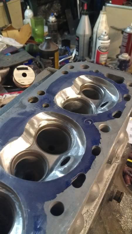
The valves have been unshrouded and the chamber walls are undercut slightly, not much has been taken from the side opposite the spark plug as I would prefer the airflow NOT enter the chamber that side...I want it to flow across the valve and enter on the spark plug side/exhaust valve side as much as possible.

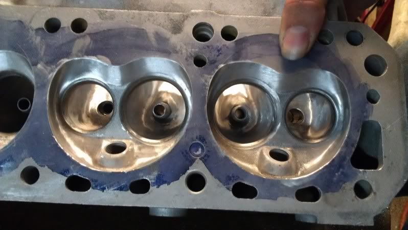
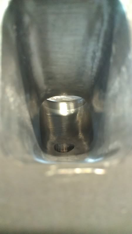
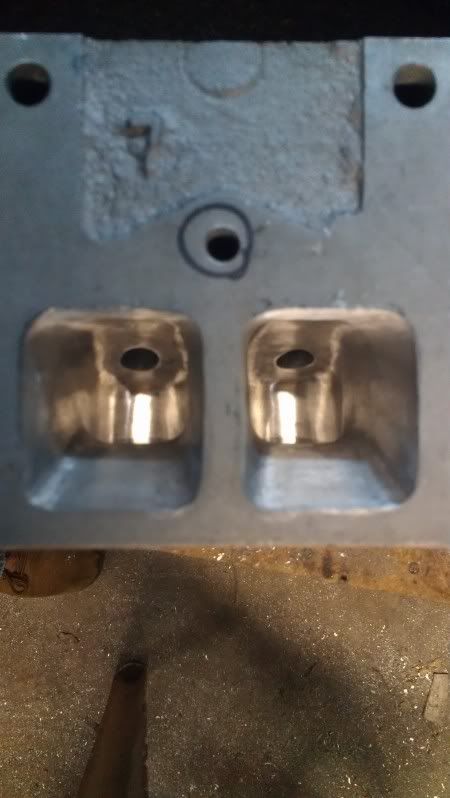
I am considering welding the spark plug boss solid and re-drilling it at an angle, bringing the plug in pointed at the exhaust valve. This would let me open the pocket up in front of the intake valve, and move the electrode out of the way of the incoming intake charge. I have a photo of a head that was done this way; and have done the welding on a spare, cracked head...Setting it up to machine the spark plug locations isn't exactly easy without having a milling machine readily available right now.

Image

Image

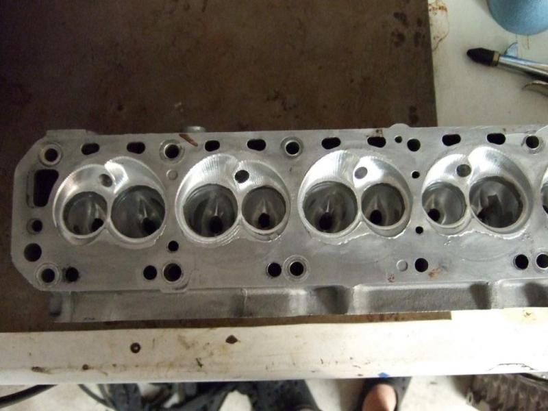
Those chambers were a prototype CNC porting method that has not been completed. That cylinder head has not been run on an engine yet; but maybe in a few years we'll see it finished up.

Thoughts? Obviously, if it's worth the better chamber shape to get a more consistent burn in this swirl-dominated system (very little tumble in the intake port on these) then I'll consider it. I am currently having issues with this engine wanting to go lean and putter in the 2500-3500RPM range; which is just when the boost is coming in...At 4000RPM, plug cuts reveal very evenly balanced chambers...but plug cuts at 2000, 2500, 3000, and 3500RPM show some cylinders very rich and some cylinders slightly rich; It's EFI and so I corrected the slightly rich chambers...but that still leaves the very rich chambers, well, rich and sooty.
ProPower engines
Guru
Guru
Posts: 8707
Joined: Sun Jan 21, 2007 1:16 pm
Location: Victoria BC Canada

Re: Chamber shaping-How good/bad can this be made to work?

Post by ProPower engines »

There is a local guy that has a pro 4 racer and he has been developing a similar head for the L series engine for the unlimited class. He had the chambers fully welded and CNC machined after several hand blended test heads.
Would it no be better to form a better quench area in the head.
The machined band on the piston depending on the width may help but not as much as having the larger quench pad on the plug side like what it used in the BB Chrysler engines. It reduced the detonation very well with a open chamber head design.

Or maybe you can get pistons made that way and save the head welding.
Since you are EFI it will give you better fuel management over a carb'd application.
Real Race Cars Don't Have Doors
JoePorting
Guru
Guru
Posts: 2997
Joined: Mon Jun 14, 2010 3:16 pm
Location: Lake Elizabeth, CA

Re: Chamber shaping-How good/bad can this be made to work?

Post by JoePorting »

I think your chamber looks fine as is. I wouldn't bother with the plug. If you want more power, cut in a new intake valve seat. Looks like you could go .100" bigger. A .100" larger intake valve should really pick up the flow and power.
Joe Facciano
PackardV8
Guru
Guru
Posts: 7633
Joined: Sun Jul 30, 2006 2:03 pm
Location: Spokane, WA

Re: Chamber shaping-How good/bad can this be made to work?

Post by PackardV8 »

Thoughts? Obviously, if it's worth the better chamber shape to get a more consistent burn in this swirl-dominated system (very little tumble in the intake port on these) then I'll consider it. I am currently having issues with this engine wanting to go lean and putter in the 2500-3500RPM range; which is just when the boost is coming in...At 4000RPM, plug cuts reveal very evenly balanced chambers...but plug cuts at 2000, 2500, 3000, and 3500RPM show some cylinders very rich and some cylinders slightly rich; It's EFI and so I corrected the slightly rich chambers...but that still leaves the very rich chambers, well, rich and sooty.
How is this a combustion chamber problem? Wouldn't one look at cam timing and intake manifold as the more likely solutions?
Jack Vines
Studebaker-Packard V8 Limited
Obsolete Engineering
Xnke
Pro
Pro
Posts: 343
Joined: Mon Aug 20, 2012 7:39 pm
Location:

Re: Chamber shaping-How good/bad can this be made to work?

Post by Xnke »

Cam timing is the current variable that I'm working on. Already worked the intake manifold problem for a while; we're on the 3rd intake. I'm just looking at ideas; the chamber is quite a bit more "closed" than the other chambers that I've used on these engines, even being a deeper chamber with more volume.

Port job is one of my better L-series jobs to date. The bench I used was starting to loose steam at 0.500" lift though, I am not so sure it isn't higher than 214CFM.

Lift - Intake Flow CFM
.1 - 62.4
.2 - 117.1
.3 - 157.8
.4 - 199.1 (FIGJAM!)
.5 - 214.1

Lift - Exhaust flow CFM
.1 -- 51.4
.2 -- 80.3
.3 -- 102.1
.4 -- 128.8
.5 -- 134.1

I was looking into the angle-plug idea to see if it was beneficial enough to be worth the effort. I think once I get the cam timing straightened out, that I can make 350-380HP from what I have, at 10-14Lbs of blower boost.
KnightEngines
Guru
Guru
Posts: 2691
Joined: Fri Jan 09, 2009 8:51 pm
Location: Australia

Re: Chamber shaping-How good/bad can this be made to work?

Post by KnightEngines »

With boost don't get too concerned about quench, it don't matter so much, at 14psi you really what you have will be fine.

Couldn't resist, here's the numbers on a U67 L20b casting I did quite a while ago:

Head flow:

Intake

Lift - flow (bare head) - flow (with intake)
.1 - 61 - 61.5
.2 - 116 - 116.4
.3 - 166.7 - 163.7
.4 - 202.4 - 197
.5 - 229 - 222
.55 - 229 - 222.4
.6 - 233 - 227
.65 - 233 - 227
.7 - 234 - 228

Exhaust

Lift - flow
.1 - 50
.2 - 86.9
.3 - 122.7
.4 - 137.7
.5 - 151
.55 - 156.8
.6 - 160
.65 - 163.2

Image

Image

Image
Xnke
Pro
Pro
Posts: 343
Joined: Mon Aug 20, 2012 7:39 pm
Location:

Re: Chamber shaping-How good/bad can this be made to work?

Post by Xnke »

JoePorting, I'd rather have a bigger exhaust valve in these heads...although the biggest you can go is 46mm intake and 38mm exhaust; once you have those in place the seats are already interlocking and you're running out of chamber room. The head in the photo is 44mm intake and 35mm exhaust; the stock exhaust seat will hold a 36.5mm valve and the stock intake seat will hold a 45mm intake valve. If you feel lucky and the seats are very, very concentric with the valve guide, you could push it out to a 37mm exhaust without changing the seats. Until my flow bench gets finished and calibrated, I won't have the tools to do proper measurements easily available. The flow numbers above are from a borrowed bench that calibrated at 100CFM at 28", which is what the ports were flowed at. The bench was running W-F-O to get the 28" at 0.500" lift.
Xnke
Pro
Pro
Posts: 343
Joined: Mon Aug 20, 2012 7:39 pm
Location:

Re: Chamber shaping-How good/bad can this be made to work?

Post by Xnke »

TK!

Was hoping you'd show up here. How did that engine go? Last I saw it was on a 2.3 LZ stroker, had ITB's bolted on, looked fantastic.

I printed those U67 photos and had them tacked up on my bench when I was doing the ports. I didn't quite make it to your numbers, my ports fall off above 0.500" lift. I'm not keen to run a cam bigger than 0.500" lift on these engines anyway, as spring life gets too short...I DO have a roller cam solution and it's currently in the testing stages. I got it to last 12 hours with no damage and minimal wear running a cast-piston L24 at 7200RPM, but that's the extent of testing so far. It still will not live on the street, and it's come down to metallurgy.
KnightEngines
Guru
Guru
Posts: 2691
Joined: Fri Jan 09, 2009 8:51 pm
Location: Australia

Re: Chamber shaping-How good/bad can this be made to work?

Post by KnightEngines »

That motor made about 210hp on pump swill I think, yep, 2.3L stroker with Munyard ITB's.

Don't go to big on the intake bowls, that kills them, but you can lay back the short turn to boost higher lift flow, you need to get into the bottom of the seat insert a little & blend it right into the bottom cut of the valve job.
On the exhaust side you lay back the turn pretty hard, the exhaust ports have a real low floor, but you can make it work if you turn the air early, short turn should start damn close to the seat contact on the exhaust.
smeg
Expert
Expert
Posts: 548
Joined: Fri Feb 09, 2007 12:43 am
Location: melbourne, Australia

Re: Chamber shaping-How good/bad can this be made to work?

Post by smeg »

TK,
that port and chamber surface sure is Purdy!
Xnke
Pro
Pro
Posts: 343
Joined: Mon Aug 20, 2012 7:39 pm
Location:

Re: Chamber shaping-How good/bad can this be made to work?

Post by Xnke »

Looks like the short turn is where my intake flow is...I barely touched it. Layed the exhaust back some, didn't take a lot of material out except around the valve guide, pulled a little (under 2mm) out of the roof and walls, widened up the port floors some and set the intake bias to push flow into the cylinder instead of the chamber wall.
JoePorting
Guru
Guru
Posts: 2997
Joined: Mon Jun 14, 2010 3:16 pm
Location: Lake Elizabeth, CA

Re: Chamber shaping-How good/bad can this be made to work?

Post by JoePorting »

Nice port work.
Joe Facciano
KnightEngines
Guru
Guru
Posts: 2691
Joined: Fri Jan 09, 2009 8:51 pm
Location: Australia

Re: Chamber shaping-How good/bad can this be made to work?

Post by KnightEngines »

Yep, I can see in your 1st pics the intake turn needs to be laid back a bit more, it's also well worth widening the window above the turn & flattening out the peak of the turn, make the turn itself quite wide, carefull if you've got a 44mm valve in there, it'll go close to water on the corners of the turn.
Exhaust doesn't need to be big, they are a decent size to start with, but that turn has to be made as wide as possible & laid back quite a lot.
Xnke
Pro
Pro
Posts: 343
Joined: Mon Aug 20, 2012 7:39 pm
Location:

Re: Chamber shaping-How good/bad can this be made to work?

Post by Xnke »

Here are a few shots of the ports; maybe this will show some of my deficiencies better.

Image

Image

Image

Image

And a shot with the little blower:

Image
mk e
Guru
Guru
Posts: 5482
Joined: Mon Sep 17, 2012 3:19 pm
Location: Elverson, PA

Re: Chamber shaping-How good/bad can this be made to work?

Post by mk e »

PackardV8 wrote:
How is this a combustion chamber problem? Wouldn't one look at cam timing and intake manifold as the more likely solutions?
+1 to the intake problem. I went round and round with this on my last custom blower setup. Now that has a V not a straight engine but the issue sounds the same.

For me I was able to change the rpm/load where I had the problem but couldn't eliminate it and finally just gave up ona mechanical solution, pick the setup where the high rpm full load was good and them upgraded the ECU to one that had the ability to tune cylinder by cylinder to clean up what was still not quite right. I use a motec M800 which I think had 12x12 cylinder tuming maps available, but that was about 8 years ago I think there are lower cost options these days, I think the MS3 has it now....but the motecs are REALLY nice if you've never used one, I just bought a M150 for the V12 I'm working on and it does just about everything, now I just need to actually FINISH the engine.
You do not have the required permissions to view the files attached to this post.
Mark
Mechanical Engineer
Post Reply