Enclosed cam tunnel installs....

General engine tech -- Drag Racing to Circle Track

Moderator: Team

Warp Speed
Guru
Guru
Posts: 3285
Joined: Wed Jun 25, 2008 1:46 pm
Location: NC

Re: Enclosed cam tunnel installs....

Post by Warp Speed »

140Air wrote:
Warp Speed wrote:
The losses from the cam and lifters being submerged is almost unmeasurable, as long as the area isn't trapped and pressurized. The losses from the top end oil raining down onto the reciprocating assembly is definatly measurable.
Hmm, lifters submerged are pumping oil, though not against pressure. Hard to believe it's unmeasurable. How much does oil dripping from the cam add to what's already entrained? Do you remember any figures on the comparison between the two cases? Also, have these measurements been made on a motored engine?
The movement and leverage of the cam and lifters is relatively small compared to the rotating assy.
You need to remember, the oil from the top end is well over 1 gpm in most all cases, higher in others. Pretty big hit when you reduce that in the crank case.
Both firing and non-firing cells used for testing.
Warp Speed
Guru
Guru
Posts: 3285
Joined: Wed Jun 25, 2008 1:46 pm
Location: NC

Re: Enclosed cam tunnel installs....

Post by Warp Speed »

Kevin Johnson wrote:
That a flooded valve train will cost power -- in this/these particular system(s) that was/were tested further suggests that it is the camshaft and/or lifters that need(s) closer attention with respect to vibration damping/control.
Doesn't seem to be the case...........
Kevin Johnson
HotPass
HotPass
Posts: 9403
Joined: Tue Nov 22, 2005 5:41 am
Location:

Re: Enclosed cam tunnel installs....

Post by Kevin Johnson »

Warp Speed wrote:
140Air wrote:
Warp Speed wrote:
The losses from the cam and lifters being submerged is almost unmeasurable, as long as the area isn't trapped and pressurized. The losses from the top end oil raining down onto the reciprocating assembly is definatly measurable.
Hmm, lifters submerged are pumping oil, though not against pressure. Hard to believe it's unmeasurable. How much does oil dripping from the cam add to what's already entrained? Do you remember any figures on the comparison between the two cases? Also, have these measurements been made on a motored engine?
The movement and leverage of the cam and lifters is relatively small compared to the rotating assy.
You need to remember, the oil from the top end is well over 1 gpm in most all cases, higher in others. Pretty big hit when you reduce that in the crank case.
Both firing and non-firing cells used for testing.
It would be simple enough to place a camshaft in a fixed tube and place this in a 55 gallon drum of oil to flood the tube with oil. The power drawn at say 4000 rpms could be directly measured and this would be less than that consumed by the same system whilst actuating lifters. Many of my old customers made small batches of product with devices of similar action. No free lunch.
https://www.semasan.com/breaking-news-archives?utm_campaign=DrivingForce_DF272&utm_content=SeeAllLeg
Warp Speed
Guru
Guru
Posts: 3285
Joined: Wed Jun 25, 2008 1:46 pm
Location: NC

Re: Enclosed cam tunnel installs....

Post by Warp Speed »

Kevin Johnson wrote: It would be simple enough to place a camshaft in a fixed tube and place this in a 55 gallon drum of oil to flood the tube with oil. The power drawn at say 4000 rpms could be directly measured and this would be less than that consumed by the same system whilst actuating lifters. Many of my old customers made small batches of product with devices of similar action. No free lunch.
The small diameter of the camshaft provides little leverage for the loss. Couple that with the cam being under driven 2-1, and the losses become very small relative to the rest of the system.
Now add rocker arms, springs and rocker ratio. More parts moving a greater distance, the losses from flooding start adding up. But they are a necessary evil in some endurance applications.
An engine is just a stack of compromises.............
Kevin Johnson
HotPass
HotPass
Posts: 9403
Joined: Tue Nov 22, 2005 5:41 am
Location:

Re: Enclosed cam tunnel installs....

Post by Kevin Johnson »

Jay, would you predict the same results with roller cams?
https://www.semasan.com/breaking-news-archives?utm_campaign=DrivingForce_DF272&utm_content=SeeAllLeg
Warp Speed
Guru
Guru
Posts: 3285
Joined: Wed Jun 25, 2008 1:46 pm
Location: NC

Re: Enclosed cam tunnel installs....

Post by Warp Speed »

Kevin Johnson wrote:Jay, would you predict the same results with roller cams?
Seems to be that way so far but................
140Air
Guru
Guru
Posts: 1542
Joined: Sun Mar 17, 2013 11:55 pm
Location:

Re: Enclosed cam tunnel installs....

Post by 140Air »

Warp Speed wrote:
Kevin Johnson wrote: It would be simple enough to place a camshaft in a fixed tube and place this in a 55 gallon drum of oil to flood the tube with oil. The power drawn at say 4000 rpms could be directly measured and this would be less than that consumed by the same system whilst actuating lifters. Many of my old customers made small batches of product with devices of similar action. No free lunch.
The small diameter of the camshaft provides little leverage for the loss. Couple that with the cam being under driven 2-1, and the losses become very small relative to the rest of the system.
Now add rocker arms, springs and rocker ratio. More parts moving a greater distance, the losses from flooding start adding up.
My question remains, what are the losses either way? Does anybody have figures? Otherwise we are just hand waving.
Robert Kane
Pro
Pro
Posts: 402
Joined: Thu Apr 28, 2005 11:46 pm
Location:

Re: Enclosed cam tunnel installs....

Post by Robert Kane »

Does anyone have pics of an enclosure, or fabricated tray for under the camshaft?

Robert.
nathanhouse
New Member
New Member
Posts: 15
Joined: Sat Oct 19, 2013 7:57 pm
Location:

Re: Enclosed cam tunnel installs....

Post by nathanhouse »

CNC BLOCKS wrote:Here is a block that came from Penske Racing years ago and is still running.

Image
Doesn't really have anything to do with the original post but also notice that the Penske block have the pan rails filled with epoxy and the more narrow areas cut away and shaped? This block was had an early segregated pan (probably multi piece steel version) and if I remember right the cam tunnels were bored so the sleeves would push in with the same press as the cam bearings and they just staked up, sleeve bearing, sleeve bearing ect... Lots of work went into these. They onlyran one scavenge that was in the right rear and ran out of the valley cover under the manifold. Did you get any of the other trick stuff that came with this engine? Pistons, lifters, rockers?
JWRE
Expert
Expert
Posts: 573
Joined: Fri Feb 09, 2007 1:42 pm
Location: Georgia

Re: Enclosed cam tunnel installs....

Post by JWRE »

Warp Speed wrote:
Kevin Johnson wrote: It would be simple enough to place a camshaft in a fixed tube and place this in a 55 gallon drum of oil to flood the tube with oil. The power drawn at say 4000 rpms could be directly measured and this would be less than that consumed by the same system whilst actuating lifters. Many of my old customers made small batches of product with devices of similar action. No free lunch.
The small diameter of the camshaft provides little leverage for the loss. Couple that with the cam being under driven 2-1, and the losses become very small relative to the rest of the system.
Now add rocker arms, springs and rocker ratio. More parts moving a greater distance, the losses from flooding start adding up. But they are a necessary evil in some endurance applications.
An engine is just a stack of compromises.............
You beat me to it Warp, I was going to post an almost identical reply. 140Air, if you figure the speed in MPH of the outer most part of the cam vs. the crank. With only 25% of the diameter and half the speed of the crank, the cam is almost sitting still compared to the couterweights of the crank. I do like how you're thinking though, considering all trade offs or downsides that come with gains. :D
User avatar
Alan Roehrich
Guru
Guru
Posts: 3069
Joined: Tue Jul 04, 2006 5:58 pm
Location: Murfreesboro TN
Contact:

Re: Enclosed cam tunnel installs....

Post by Alan Roehrich »

maxracesoftware wrote: ( Penske Racing ) , and you already know its worth potential HP , that's reason for asking about it .
back-to-back BBC Chevy Dyno test at 8000 RPM Peak 1380 HP was a solid 25 HP gain ( 1.140" Lift Solid Roller Cam w/Dry Sump )

just need to make sure Flat tappet cam can live

Seriously considering this on my SS/EA 396/375 engine, with stock diameter cam, and 0.904" lifters. Between that, a crankshaft scraper, and the dividers in the oil pan, I hope to see a little gain.

Not sure what we might see. We've only got 750+ HP, at 8100. But we cannot knife edge the crank, or do any other tricks of that nature, legally. Of course, we do only have a 3.775"stroke, and the bore is only 4.165", so there's not so much going on in the pan as you'd see with that big HP engine. Then again, we have a wet sump, and cannot even run a vacuum pump. This might be interesting.

Tried it a while back on a 427/425HP stocker engine. However, we had an unhappy circumstance (driver error) that killed that engine at the track before any real testing took place, and we're not sure what the other changes did anyway. Might try it on a new 396/375 stocker engine though.
Kevin Johnson
HotPass
HotPass
Posts: 9403
Joined: Tue Nov 22, 2005 5:41 am
Location:

Re: Enclosed cam tunnel installs....

Post by Kevin Johnson »

JWRE wrote:
Warp Speed wrote:
Kevin Johnson wrote: It would be simple enough to place a camshaft in a fixed tube and place this in a 55 gallon drum of oil to flood the tube with oil. The power drawn at say 4000 rpms could be directly measured and this would be less than that consumed by the same system whilst actuating lifters. Many of my old customers made small batches of product with devices of similar action. No free lunch.
The small diameter of the camshaft provides little leverage for the loss. Couple that with the cam being under driven 2-1, and the losses become very small relative to the rest of the system.
Now add rocker arms, springs and rocker ratio. More parts moving a greater distance, the losses from flooding start adding up. But they are a necessary evil in some endurance applications.
An engine is just a stack of compromises.............
You beat me to it Warp, I was going to post an almost identical reply. 140Air, if you figure the speed in MPH of the outer most part of the cam vs. the crank. With only 25% of the diameter and half the speed of the crank, the cam is almost sitting still compared to the couterweights of the crank. I do like how you're thinking though, considering all trade offs or downsides that come with gains. :D
Well, it is not so simple. The rotating assembly at speed is pulverizing the 1-gallon-per-minute draining oil and the resulting droplet size is allowing the oil to be drawn back in and replenish or maintain the oil entrainment at a higher equilibrium point. If it is a high depression dry sump then the action would be mainly friction. Jay works on many sorts of engines so this is unknown.

A better experiment might be to use a CNC router and lop off a cam to make a rotating element. The current draw at a constant speed under varying conditions could be established and a relative percentage loss determined with simple or complex housings. The adding of the interference of the flat lifter to this should be significant (relatively) and then the roller type element even more so because of the added surface area, entrainment and turbulence. This jig would need to have sufficient spring pressure to avoid lofting the lifter but the nice thing is that you could then directly calculate friction losses for a given profile and spring pressure versus rpm (and oil type or temp if you wished).

The design of the enclosure, though, is really important and was alluded to by making sure the system is not pressurized. After all, it is the enclosed nature of the crankcase and rotating assembly that moves it to the Tea Leaf paradox rather than simple rivulet and droplet generation and impact whilst on a tangential exit. And then, what does "flooded" really mean?

I am still suspicious that the torsional/damping dynamics of a flooded cam are creating a confound and affecting the power output which is not accounted for save by careful experimental design. When answers are in the form of " yes ... but ..........." rather than an explication of the design this is a valid concern.

"Yes, but" is normally the province explored when you find out that all those laws and handy algorithms are riddled with important exceptions. :lol:
https://www.semasan.com/breaking-news-archives?utm_campaign=DrivingForce_DF272&utm_content=SeeAllLeg
140Air
Guru
Guru
Posts: 1542
Joined: Sun Mar 17, 2013 11:55 pm
Location:

Re: Enclosed cam tunnel installs....

Post by 140Air »

Warp Speed wrote:
Kevin Johnson wrote:
The small diameter of the camshaft provides little leverage for the loss. Couple that with the cam being under driven 2-1, and the losses become very small relative to the rest of the system.............
]

Well, it is not so simple. The rotating assembly at speed is pulverizing the 1-gallon-per-minute draining oil and the resulting droplet size is allowing the oil to be drawn back in and replenish or maintain the oil entrainment at a higher equilibrium point. If it is a high depression dry sump then the action would be mainly friction. ...
I am still suspicious that the torsional/damping dynamics of a flooded cam are creating a confound and affecting the power output which is not accounted for save by careful experimental design. When answers are in the form of " yes ... but ..........." rather than an explication of the design this is a valid concern. :lol:
Excellent thoughts Kevin. It is not good engineering to do speculative design, treating assumed problems with hunch solutions without measuring anything. But, this is done frequently. Progress is made despite false leads and blind alleys. This is a tradeoff, a cost and a benefit, not a simple win.
JWRE
Expert
Expert
Posts: 573
Joined: Fri Feb 09, 2007 1:42 pm
Location: Georgia

Re: Enclosed cam tunnel installs....

Post by JWRE »

Yes Kevin, I'm aware that's its a lot more complicated than I explained. I was only trying to keep things simple for the sake of staying on topic. Now you've made this post probably end up being 20 pages talking about 10 topics. :D But, that's usually a good thing as it brings in the better minds of Speed Talk so I can expect to learn something new.
blykins
Guru
Guru
Posts: 2130
Joined: Mon Aug 27, 2007 9:59 pm
Location: Louisville, KY

Re: Enclosed cam tunnel installs....

Post by blykins »

Alright, here's an update to all this cam tunnel lingo...

The block I am doing this for is an FE block. 75% of my stuff is FE, so I figured it would be some good R&D for some future race engine builds, and would give me something to play with here.

Instead of using a sheet metal half pipe between the bulkheads, I went about it in this direction:

The tunnel is the cam bearing...

Image

Image

Image

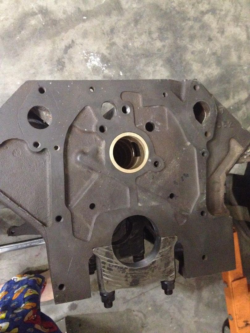
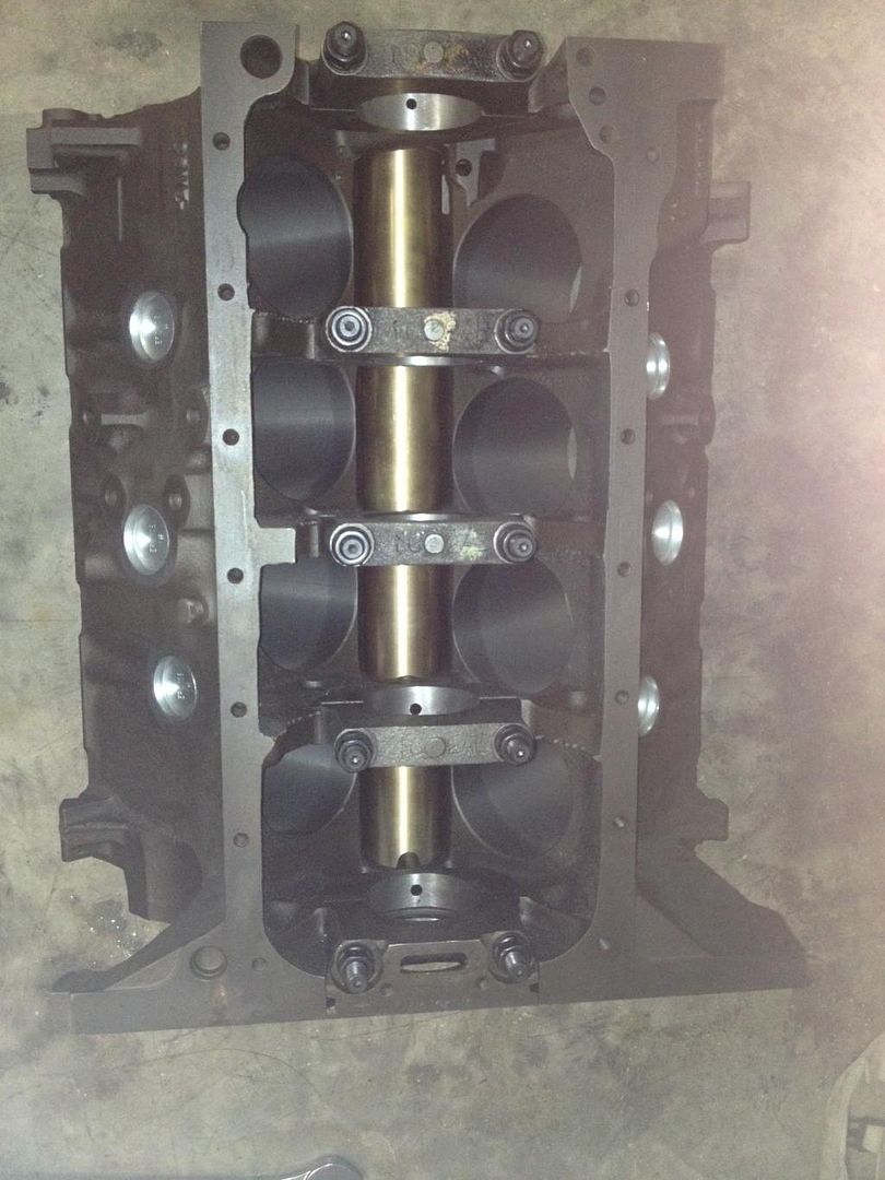
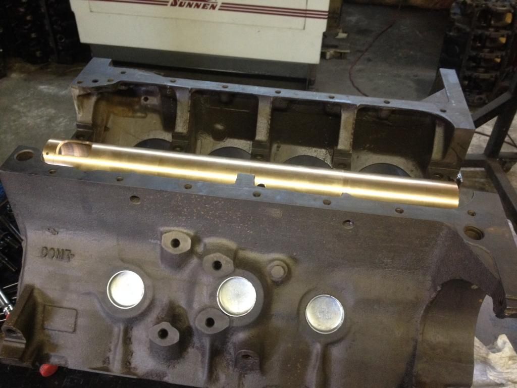
The ID of an FE cam tunnel is stepped. That actually helped things out, so instead of trying to press fit an entire tube, the tube basically drops in until the last 5/8" and then is a press fit. The tube is stepped, basically with the same OD as the cam bearings.

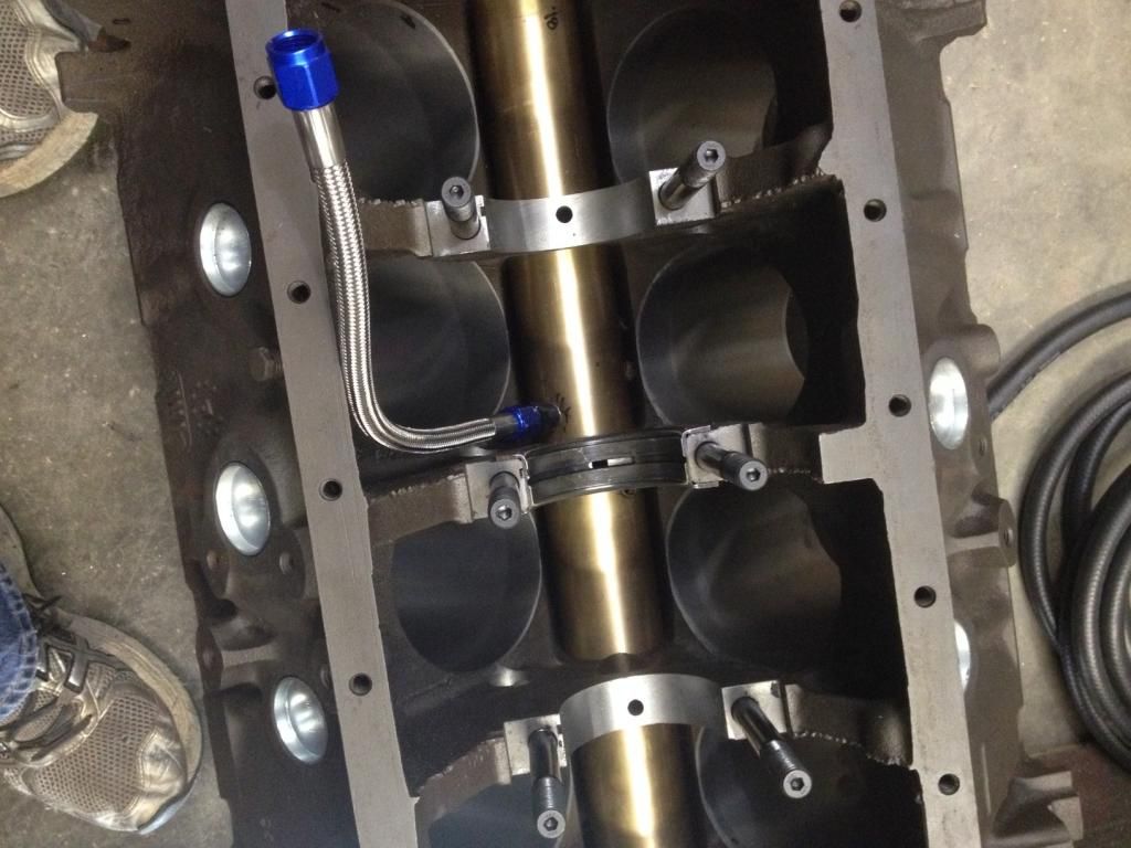
Holes are drilled from the mains to the cam to feed the oil, and all the necessary grooves on the front of the tunnel are there to oil the distributor and timing set.

The lifter valley will be more or less sealed off. The drain holes in the block were candidates for 3/4" cup plugs and the heads will drain straight to the pan.

To install, I just slip it in, then draw it in with a roller cam bearing tool. Pretty simple. We bored the lifter bores for bronze bushings, so the bores were opened up, the cam tunnel installed, then the cam tunnel was bored for lifter holes, then the bushings were pressed in. They extend down into the tunnel. This of course was all done with a BHJ lifter tru fixture.

To drain the tunnel, I drilled and tapped the tunnel for (2) 1/4" NPT holes, right on the front and back side of the thrust bearing bulkhead. There's plenty of room there, and I can drain the tunnel through (2) -6AN hoses that attach near the pan rail and empty straight into the oil pan out of the way of the rotating assembly.

Image

Got a little head and intake work to finish, but I hope to have it running soon. Rotating assembly is here, camshaft is here, just need to finalize some things.
Lykins Motorsports
brent@lykinsmotorsports.com
www.lykinsmotorsports.com
www.customfordcams.com
Custom Ford Windsor, Cleveland, and FE Street/Race Engines
Post Reply