
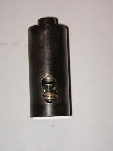


Inside the body at the bottom, visible through the figure-8 hole is the fine thread cut inside, locating a fixed piece.
Also inside the body about one-third the way down, there's a tiny locating pin pressed in through a hole in the side of the body.
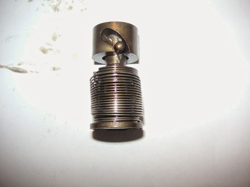
To further complicate things, the engine had adjustable pushrods, suggesting they aren't true hydraulic lifters.
Ever seen anything like this? Who made it and why?


