Mid-lift vs Low-pivot rocker arm geometry

General engine tech -- Drag Racing to Circle Track

Moderator: Team

User avatar
skrunk
New Member
New Member
Posts: 42
Joined: Fri Oct 07, 2016 4:07 am
Location: Melbourne
Contact:

Re: Mid-lift vs Low-pivot rocker arm geometry

Post by skrunk »

Topical thread as I've designed and made my own high ratio rockers and learnt a sh*t load in the process.
In my case 'the perfect geometry' gave way to packaging constraints: Huge included valve angle, skinny pushrod tube to house my fat tapered pushrods and a bunch of other factors that led to a rather compromised geometry on the valve side.

A point that became very obvious early in the design process, and has been mentioned here a couple times, is the importance of the pushrod side geometry. This is critical. Small changes are amplified through the RR to become big upsets at the valve. 90 deg at mid lift is the most faithful means of transmitting cam information while minimising lateral pushrod movement. The latter point being particularly important in my case.

So I concentrated on getting the pushrod side right then dealt with the consequences on the other side. What I eventually (and I mean eventually!) ended up with is what the OP mentioned as 'low pivot'. But really low. In my case the 90 deg point isn't around Jesel's 2/3's lift range, but just a few cam degrees before max lift. However, this could prove advantageous when you consider maximum piston speed or piston demand.

An observation before I go on: It's an easy habit to think of rocker ratio in terms of lift and forget the huge influence on duration at the valve - arguably more important because, as I see it, it is the stretched duration that contributes most to the area under the curve. The 90 degree point dictates the position of maximum stretch so wouldn't it make sense to put that stretch at the point of maximum piston speed i.e. max piston demand? Is that not Jesel's thinking? (I know there is inertial delay thrown into the equation). A fun thought experiement if nothing else.

The V8 guys among you (i.e. all of you :lol: ) seem to like cam splits of 110 deg or there abouts (?). So, depending on the timing, the max piston speed ocures around the 'Jesel point' ??? In my case LSA=104 deg and the point of max piston speed is way up close to max lift which happens also to be around the 90deg point. A happy coincidence I confess, not by design.

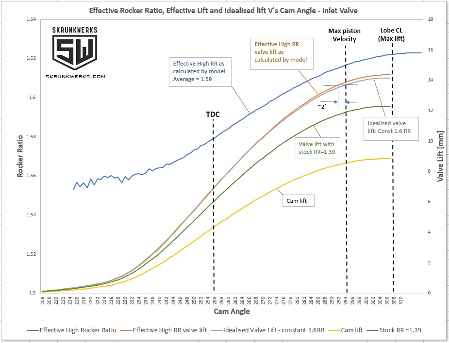
The graph below shows the actual effective RR as the rocker rotates through it's arc. The RR varies from ~1.56 at open through to 1.62 at peak lift. As an exersise I compared this with an idealised curve with constant RR of 1.6 (which was my target RR). As expected, not much in the flanks though you can see the curves cross a few degrees before TDC. The action occures closer to max lift where the 90 deg point is. At max piston speed an increase in duration of approx 2 deg (half the cam) is apparent. That's 8 deg at the crank.

Whether any of this makes a zack of difference is the question. A fun academic exersise with results lost in dyno noise between pulls? Particularly in my case where gains are in the upper portion of the lift profile - not as much bang for buck as in the 'body' of the profile. Haven't tested them yet - we'll see.

Image
Last edited by skrunk on Mon May 13, 2019 8:44 am, edited 1 time in total.
Warp Speed
Guru
Guru
Posts: 3285
Joined: Wed Jun 25, 2008 1:46 pm
Location: NC

Re: Mid-lift vs Low-pivot rocker arm geometry

Post by Warp Speed »

Proper valve motion is the cams job, relaying this motion, the most efficient way, is the rockers job.
..
paulzig
Expert
Expert
Posts: 643
Joined: Sun Aug 03, 2008 6:29 am
Location: Australia

Re: Mid-lift vs Low-pivot rocker arm geometry

Post by paulzig »

Does the mid-lift method put the rocker at 90°to the valve close to the MAX velocity of the lobe?
User avatar
MadBill
Guru
Guru
Posts: 15024
Joined: Tue Nov 15, 2005 10:41 am
Location: The Great White North

Re: Mid-lift vs Low-pivot rocker arm geometry

Post by MadBill »

In this diagram: https://www.google.ca/search?q=engine+v ... BOj6hzN9KM: opening side velocity (red line) peaks just before the half lift point (~30° ATDC) where mid lift theory calls for a 90° contact angle.
Felix, qui potuit rerum cognscere causas.

Happy is he who can discover the cause of things.
User avatar
skrunk
New Member
New Member
Posts: 42
Joined: Fri Oct 07, 2016 4:07 am
Location: Melbourne
Contact:

Re: Mid-lift vs Low-pivot rocker arm geometry

Post by skrunk »

Here's is how I see it.
Rocker ratio moves through a range and is maximised at the 90* point. (actually, that depends a bit on the interplay of geometry on the valve and pushrod sides) This is where everything else is maximised in terms of that range - lift, velocity, acceleration, jerk and as a consequence and most importantly, duration.

I'm not sure that putting the 90* point at the maximum lobe lift velocity should necessarily be a goal in and of itself? Three reasons:

1) It's more a matter of deciding where to put the 90* max rocker range point (max piston vel?) according to a particular engine architecture But only if you believe doing so makes discernible difference to engine output. The jury is still out for me on this one. Does anyone (Jesel?) have any hard evidence that this is the case?

2) Putting the 90* point at around the max lobe velocity happens to correspond roughly to mid lift which happens to be where geometry is optimised in terms of more faithfully conveying cam info and reducing things such as lateral pushrod movement and travel across the valve tip face. i.e optimising valve train stability, which I think is the main game. It just happens to sometimes, approximately coincide with max lobe velocity. No. 1) mucks around with this geometry. Yes, heard alternatives re positioning rocker tip in relation to spring load and avoiding changing direction on the valve tip etc.

3) Putting the 90* max rocker range point at mid lift (which happens to sometimes coincide with ~max lobe vel) fattens the duration in the flanks and exposes the lobe lift curve to the highest rocker ratio range which results in optimised area under the curve where you want it in the body of the curve rather than in the nose and early lift stages..

Anyway, that's my thought bubble. Fire at will..
Warp Speed
Guru
Guru
Posts: 3285
Joined: Wed Jun 25, 2008 1:46 pm
Location: NC

Re: Mid-lift vs Low-pivot rocker arm geometry

Post by Warp Speed »

You design the cam to give the needed valve motion. The rest of the system (pushrods, rockers) is there just to relay the message as efficiently as possible, without creating anymore unwanted dynamics than are already present. You can manipulate things with rocker design and set-up, but its typically just a band aid for some other short coming or inefficiency.
User avatar
skrunk
New Member
New Member
Posts: 42
Joined: Fri Oct 07, 2016 4:07 am
Location: Melbourne
Contact:

Re: Mid-lift vs Low-pivot rocker arm geometry

Post by skrunk »

@Warp Speed. Yes. This is basically what I was saying. Whether scrificing some efficiency (in terms of conveying cam info) and stablility i.e. deviating from the mid lift scenario where duration is optimised, will bear worthwhile gains for a particular engine. Even if the cam is well optimised?
Also wanted to make the point that putting the 90* point at max lobe velocity is, in my view, co-incidental.
paulzig
Expert
Expert
Posts: 643
Joined: Sun Aug 03, 2008 6:29 am
Location: Australia

Re: Mid-lift vs Low-pivot rocker arm geometry

Post by paulzig »

Warp Speed wrote: Tue May 14, 2019 9:35 pm without creating anymore unwanted dynamics than are already present.
You mean like harmonics, the rocker pushing back against the stud or shaft does this play a part?
GARY C
HotPass
HotPass
Posts: 6302
Joined: Tue May 14, 2013 10:58 pm
Location:

Re: Mid-lift vs Low-pivot rocker arm geometry

Post by GARY C »

Warp Speed wrote: Tue May 14, 2019 9:35 pm You design the cam to give the needed valve motion. The rest of the system (pushrods, rockers) is there just to relay the message as efficiently as possible, without creating anymore unwanted dynamics than are already present. You can manipulate things with rocker design and set-up, but its typically just a band aid for some other short coming or inefficiency.
Would that be a bandaid or just the next step in maximizing power beyond the limitations of the cam lobe itself?
Please Note!
THE ABOVE POST IN NO WAY REFLECTS THE VIEWS OF SPEED TALK OR IT'S MEMBERS AND SHOULD BE VIEWED AS ENTERTAINMENT ONLY...Thanks, The Management!
User avatar
skrunk
New Member
New Member
Posts: 42
Joined: Fri Oct 07, 2016 4:07 am
Location: Melbourne
Contact:

Re: Mid-lift vs Low-pivot rocker arm geometry

Post by skrunk »

GARY C wrote: Wed May 15, 2019 2:31 am
Warp Speed wrote: Tue May 14, 2019 9:35 pm You design the cam to give the needed valve motion. The rest of the system (pushrods, rockers) is there just to relay the message as efficiently as possible, without creating anymore unwanted dynamics than are already present. You can manipulate things with rocker design and set-up, but its typically just a band aid for some other short coming or inefficiency.
Would that be a bandaid or just the next step in maximizing power beyond the limitations of the cam lobe itself?
Basically same question I posed but your word economy much better!
Warp Speed
Guru
Guru
Posts: 3285
Joined: Wed Jun 25, 2008 1:46 pm
Location: NC

Re: Mid-lift vs Low-pivot rocker arm geometry

Post by Warp Speed »

GARY C wrote: Wed May 15, 2019 2:31 am
Warp Speed wrote: Tue May 14, 2019 9:35 pm You design the cam to give the needed valve motion. The rest of the system (pushrods, rockers) is there just to relay the message as efficiently as possible, without creating anymore unwanted dynamics than are already present. You can manipulate things with rocker design and set-up, but its typically just a band aid for some other short coming or inefficiency.
Would that be a bandaid or just the next step in maximizing power beyond the limitations of the cam lobe itself?
If the combination want a different valve motion, it needs a different cam, not a less than optimal geometry in the rocker to achieve it.
Warp Speed
Guru
Guru
Posts: 3285
Joined: Wed Jun 25, 2008 1:46 pm
Location: NC

Re: Mid-lift vs Low-pivot rocker arm geometry

Post by Warp Speed »

paulzig wrote: Wed May 15, 2019 12:30 am
Warp Speed wrote: Tue May 14, 2019 9:35 pm without creating anymore unwanted dynamics than are already present.
You mean like harmonics, the rocker pushing back against the stud or shaft does this play a part?
Don't really think "harmonics" is the correct word. More like unwanted motion and stresses. You have to remember, this is all taking place many, many times per second, and we are at the mercy of the valve spring. Harmonics and vibrations are a whole nother part of the challenge.
paulzig
Expert
Expert
Posts: 643
Joined: Sun Aug 03, 2008 6:29 am
Location: Australia

Re: Mid-lift vs Low-pivot rocker arm geometry

Post by paulzig »

Warp Speed wrote: Wed May 15, 2019 5:00 am [

If the combination want a different valve motion, it needs a different cam, not a less than optimal geometry in the rocker to achieve it.
..and if you cant get the 100% correct valve motion cut the seats 50°. :D
GARY C
HotPass
HotPass
Posts: 6302
Joined: Tue May 14, 2013 10:58 pm
Location:

Re: Mid-lift vs Low-pivot rocker arm geometry

Post by GARY C »

paulzig wrote: Wed May 15, 2019 4:24 pm
Warp Speed wrote: Wed May 15, 2019 5:00 am [

If the combination want a different valve motion, it needs a different cam, not a less than optimal geometry in the rocker to achieve it.
..and if you cant get the 100% correct valve motion cut the seats 50°. :D
I am sorry I was thinking mostly in terms of the cam and rocker ratio timing the window area to piston demand and not geometry.

Warp or others is you geometry concern how the installer might try to tweak the install or is it more of a concern about an inherent flaw in the rockers design itself?
Please Note!
THE ABOVE POST IN NO WAY REFLECTS THE VIEWS OF SPEED TALK OR IT'S MEMBERS AND SHOULD BE VIEWED AS ENTERTAINMENT ONLY...Thanks, The Management!
Warp Speed
Guru
Guru
Posts: 3285
Joined: Wed Jun 25, 2008 1:46 pm
Location: NC

Re: Mid-lift vs Low-pivot rocker arm geometry

Post by Warp Speed »

paulzig wrote: Wed May 15, 2019 4:24 pm
Warp Speed wrote: Wed May 15, 2019 5:00 am [

If the combination want a different valve motion, it needs a different cam, not a less than optimal geometry in the rocker to achieve it.
..and if you cant get the 100% correct valve motion cut the seats 50°. :D
They should already be 50.......... :wink:
Post Reply